
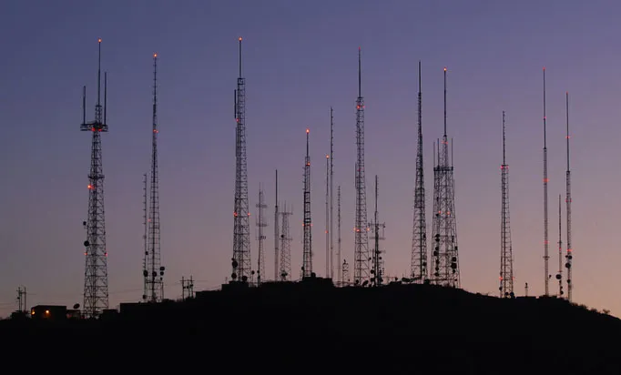
Antennas
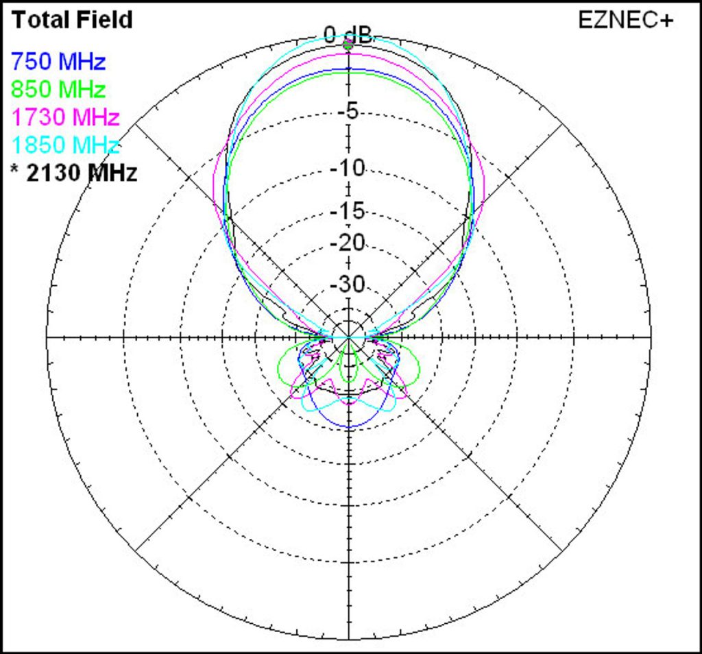
Radiation pattern
In the field of antenna design the term radiation pattern (or antenna pattern or far-field pattern) refers to the directional (angular) dependence of the strength of the radio waves from the antenna or other source.
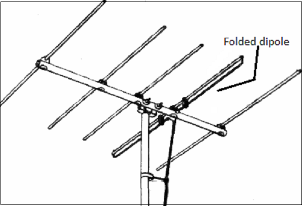
Dipol
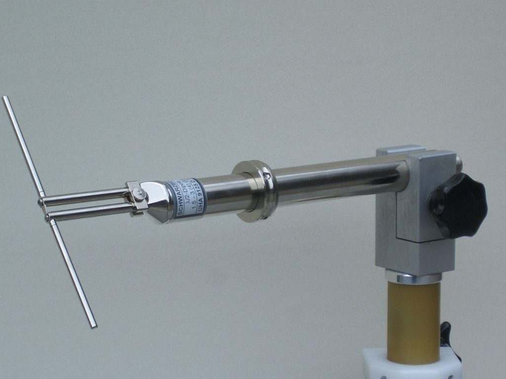
In radio and telecommunications a dipole antenna or doublet is the simplest and most widely used class of antenna. The dipole is any one of a class of antennas producing a radiation pattern approximating that of an elementary electric dipole with a radiating structure supporting a line current so energized that the current has only one node at each end. A dipole antenna commonly consists of two identical conductive elements such as metal wires or rods. The driving current from the transmitter is applied, or for receiving antennas the output signal to the receiver is taken, between the two halves of the antenna. Each side of the feedline to the transmitter or receiver is connected to one of the conductors. This contrasts with a monopole antenna, which consists of a single rod or conductor with one side of the feedline connected to it, and the other side connected to some type of ground. A common example of a dipole is the “rabbit ears” television antenna found on broadcast television sets
Isotropic radiator
An isotropic radiator is a theoretical point source of electromagnetic or sound waves which radiates the same intensity of radiation in all directions. It has no preferred direction of radiation. It radiates uniformly in all directions over a sphere centered on the source. Isotropic radiators are used as reference radiators with which other sources are compared, for example in determining the gain of antennas. A coherent isotropic radiator of electromagnetic waves is theoretically impossible, but incoherent radiators can be built. An isotropic sound radiator is possible because sound is a longitudinal wave.
Omnidirectional
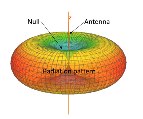
In radio communication, an omnidirectional antenna is a class of antenna which radiates equal radio power in all directions perpendicular to an axis (azimuthal directions), with power varying with angle to the axis (elevation angle), declining to zero on the axis. When graphed in three dimensions (see graph) this radiation pattern is often described as doughnut-shaped. Note that this is different from an isotropic antenna, which radiates equal power in all directions, having a spherical radiation pattern.
Directional / Beam
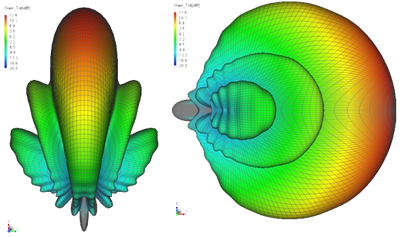
A directional antenna or beam antenna is an antenna which radiates or receives greater power in specific directions allowing increased performance and reduced interference from unwanted sources. Directional antennas provide increased performance over dipole antennas—or omnidirectional antennas in general—when greater concentration of radiation in a certain direction is desired.
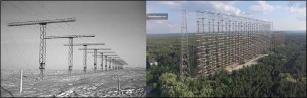
Antenna arrays
An antenna, when individually can radiate an amount of energy, in a particular direction, resulting in better transmission, how it would be if few more elements are added it, to produce more efficient output. It is exactly this idea, which led to the invention of Antenna arrays.
An antenna array can be better understood by observing the following images. Observe how the antenna arrays are connected.
Smart Antennas
Smart antennas (also known as adaptive array antennas, digital antenna arrays, multiple antennas and, recently, MIMO) are antenna arrays with smart signal processing algorithms used to identify spatial signal signatures such as the direction of arrival (DOA) of the signal, and use them to calculate beamforming vectors which are used to track and locate the antenna beam on the mobile/target. Smart antennas should not be confused with reconfigurable antennas, which have similar capabilities but are single element antennas and not antenna arrays.
Antenna Gain
In electromagnetics, an antenna’s gain is a key performance parameter which combines the antenna‘s directivity and radiation efficiency. The term power gain has been deprecated by IEEE.[1] In a transmitting antenna, the gain describes how well the antenna converts input power into radio waves headed in a specified direction. In a receiving antenna, the gain describes how well the antenna converts radio waves arriving from a specified direction into electrical power. When no direction is specified, gain is understood to refer to the peak value of the gain, the gain in the direction of the antenna’s main lobe. A plot of the gain as a function of direction is called the antenna pattern or radiation pattern. It is not to be confused with directivity, which does not take an antenna’s radiation efficiency into account.
Gain or ‘absolute gain’ is defined as “The ratio of the radiation intensity in a given direction to the radiation intensity that would be produced if the power accepted by the antenna were isotropically radiated”.[1] Usually this ratio is expressed in decibels with respect to an isotropic radiator (dBi). An alternative definition compares the received power to the power received by a lossless half-wave dipole antenna, in which case the units are written as dBd. Since a lossless dipole antenna has a gain of 2.15 dBi, the relation between these units is {\displaystyle \mathrm {Gain(dBd)} \approx \mathrm {Gain(dBi)} -2.15} . For a given frequency, the antenna’s effective area is proportional to the gain. An antenna’s effective length is proportional to the square root of the antenna’s gain for a particular frequency and radiation resistance. Due to reciprocity, the gain of any antenna when receiving is equal to its gain when transmitting.
G_{dB}=10log_{10}(\frac{P_{out}}{P_{in}})L_{dB}=-10log_{10}(\frac{P_{out}}{P_{in}})Example: If a signal with a power level of 10mW is given onto a transmission line and the measured power at some distance away is 5mW, What is loss?
L_{dB}=-10log(\frac{10}{5})=-3.01dBdBW-notation
The absolute decibel level power in dBW
Power dBW = 10 log(\frac{Power~W}{1W} )Example: Consider a directional antenna that has a gain of 6dB over a reference antenna and that radiates 700W … much power must reference antenna radiate to provide the same signal power in preferred direction?
6=10log\frac{P_2}{700}\\~\\
P_2/700=10^{0.6}=3.98\\~\\
P_2 \cong 2786W
Effective Area of Antenna(Ae)
Efffective area of an antenna is related to the physical size of antenna and to its shape. The relationship between gain and Ae is:
G=\frac{4 \pi Ae}{\lambda^2} = \frac{4 \pi f^2Ae}{c^2}\begin{align*}
& Ae:effective~area~(m^2) \\
& G:antenna~gain~(ratio) \\
& f:carrier~frequency~(Hz) \\
& c:speed~of~light~(\cong 3*10^8~m/s) \\
& \lambda:carrier~wavelength~(m) \\
\end{align*}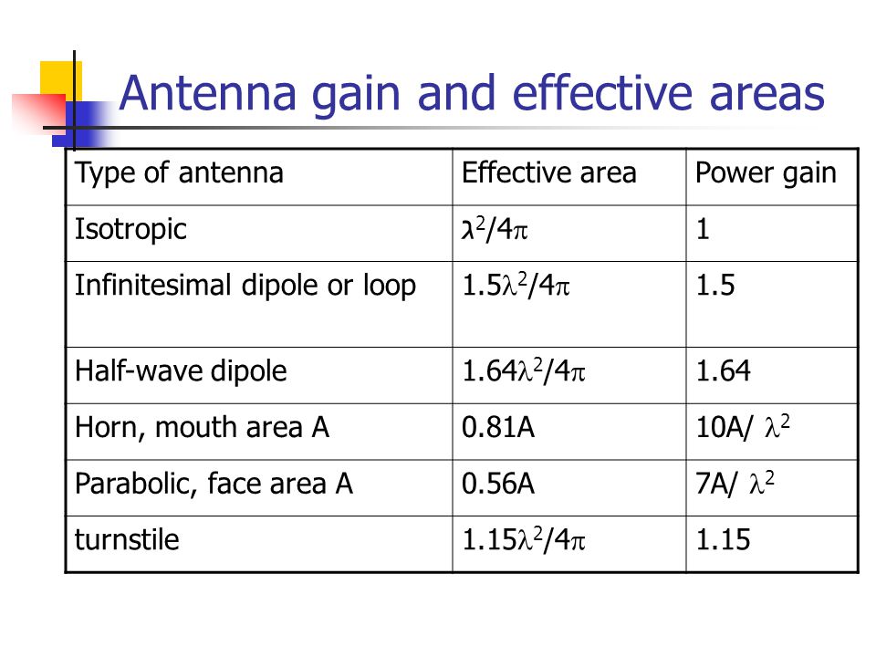
Example: For a parabolic reflective antenna with a diameter of 2m operating at 12 GHz
-what is Ae?
-what is G?
\lambda = \frac{c}{f} = \frac{3*10^8m/s}{12*10^9} = 0.25m\begin{align*}
& r=1m \\
& A=\pi r^2=\pi \\
& Ae=0.56A=0.56\pi \\
\end{align*}G= \frac{7A}{\lambda^2} = \frac{7\pi}{(0.025)^2} =35.186dB=10log(35.186)\cong 45.45dB
Leave a Reply